Subsystem Optimization Implies System Suboptimization: Not!
A. Wayne Wymore, Phd Professor of Systems Engineering, Emeritus The University of Arizona 4301 North Camino Kino Tucson AZ 85718-6657, USA voice: 520 299 6663 email: wayne@sie.arizona.edu
ABSTRACT
Conventional systems engineering wisdom has it that if subsystems are optimized, then the system cannot be optimum. This "folk theorem" has a corollary: During the system test and integration phase, the subsystems must be "balanced away" from optimum in order to optimize the system. The purpose of this paper is to show that conventional wisdom is mistaken and how it is possible for systems engineering to ensure that optimum design of the subsystems can result in optimum design of the system. The key to this happy condition is, of course, the proper allocation of the system requirements to the subsystems, or properly to derive the requirements for the design of the subsystems from the requirements for the system. In this paper, sufficient conditions for proper allocation of system requirements are specified in terms of a mathematical definition of the tradeoff concept.
THE SYSTEMS ENGINEERING CONTEXT
There is a persistent belief in the systems engineering community that the performance of a system to be designed can only be optimized at the expense of the performance of its subsystems. The purpose of this paper is to show that this "folk theorem" is not necessarily true and how it is possible for systems engineering to ensure that optimization of the subsystems can result in optimization of the total system.
That optimization of the subsystems can result in optimization of the total system is most important for phase 3 of the system life cycle, the Full Scale Engineering Design phase:
In phase 1, systems engineering develops the requirements for the overall system.
In phase 2, systems engineering specifies the subsystem architecture and derives the requirements for the design of the subsystems from the overall requirements.
In phase 3, a team is assigned to each subsystem to work, as independently as possible, on the detailed design of the subsystems on the basis of requirements derived by systems engineering (Wymore, 1993, pages 20-52).
If each team can work to find the best design for its subsystem, then phase 3 supervision and coordination of the teams by systems engineering will be easier because the interfaces between the teams can be simpler. Otherwise, extensive interaction between the teams would be required to "balance" the performance of the subsystem designs so that the top level system design will be as close to optimum as possible.
The "balancing" of the "real" subsystems during phase 5, system test and integration, will be faster and cheaper - and perhaps unnecessary - if optimum design of the subsystems implies optimum design of the system.
The whole acquisition cycle will take less time and cost less if each team can be given requirements for its subsystem with respect to which the team can optimize the design of its subsystem with the assurance that if they do then the overall system will also be optimized.
THE SYSTEM THEORETIC CONTEXT
Let SDR0 denote the system design requirements for the overall system with the structure SDR0=(IOR0, TYR0, PR0, CR0, TR0, STR0)where IOR0 is the I/O requirement, TYR0 is the technology requirement, PR0 is the performance requirement, CR0 is the cost requirement, TR0 is the tradeoff requirement and STR0 is the system test requirement. In (Wymore, 1993) a mathematical structure for each of these requirements is developed. An elementary introduction to many of the concepts discussed here can be found in (Chapman, et al, 1992).
The Space of Functional System Designs
The I/O requirement, IOR0, determines the space of all functional system designs; a functional system design is herein denoted FSD0i, where i is an integer to distinguish different functional system designs in the same discussion. (The presence of the index i does not imply that the space of functional system designs has been or even can be enumerated; indeed, that space is either empty or has an infinite number of elements (Wymore, 1993, pages 303-304).)
The Performance Requirement
The performance requirement PR0 is defined so that any two functional system designs can be compared with respect to performance. PR0 is a mathematical order (Wymore, 1993, page 532) over the space of functional system designs, that is, PR0 is a function defined for every pair of functional system designs and takes on only two values, 0 or 1:
If FSD01 and FSD02 are two functional system designs for the system and
PR0(FSD01, FSD02) = 1, then we say that FSD01 is less than or equal to FSD02 with respect to performance, or modulo performance, and write, FSD01 .LE. FSD02 MOD PR0.
If PR0(FSD01, FSD02) = 1 and
PR0(FSD02, FSD01) = 1, then we say that FSD01 and FSD02 are equivalent modulo performance and write
FSD01
== FSD02 MOD PR0.
If PR0(FSD01, FSD02) = 1 and
PR0(FSD02, FSD01) = 0, then we say that FSD02 is preferred to FSD01 modulo performance and write FSD01 < FSD02 MOD PR0.
If PR0(FSD01, FSD02) = 0 and
PR0(FSD02, FSD01) = 0, then we say that FSD01 and FSD02 are not comparable modulo performance and write
FSD1 NTC FSD02 MOD PR0.
In addition, PR0 must be reflexive:
PR0(FSD0i, FSD0i) = 1, and transitive:
if PR0(FSD0i, FSD0j) = 1 and
PR0(FSD0j, FSD0k) = 1, then
PR0(FSD0i, FSD0k) = 1.
The Overall Performance Figure of Merit
The most straightforward way for systems engineering to define PR0 is in terms of an overall performance figure of merit, PFM0R0, defined over the space of all functional system designs with values in the interval of real numbers between 0 and 1, inclusive (in order to provide a bounded range and for tie-ins to the theories of utility and of fuzzy sets), denoted RLS[0, 1].
The notation PFM0R0 tells us that we are dealing with the zeroth (PFM0R0) Performance Figure of Merit for the system design requirements SDR0. Systems engineering typically must deal with more than one set of system design requirements and more than one figure of merit in a discussion.
PFM0R0 is usually defined as a combination of other performance figures of merit denoted PFMmR0, where m is a distinguishing index not 0, representing such characteristics, for examples, as quality of service, speed of service, capacity for service, grade of service, reliability, availability and maintainability of service, incorporating the baselines and thresholds, including the "shalls," for these characteristics. PFM0R0 can be normalized so that a larger value of PFM0R0 always means better performance. Techniques for defining PFM0R0 are discussed in (Wymore, 1993, pages 383-402).
In terms of PFM0R0 we define the performance requirement PR0 as follows:
PR0(FSD01, FSD02) = 1 if and only if
PFM0R0(FSD01) .LE. PFM0R0(FSD02);
otherwise, PR0(FSD01, FSD02) = 0. In this case we say that the order PR0 is generated by the real-valued function PFM0R0 and write PR0 = RFO(PFM0R0).
Note that the performance requirement, PR0, is not the same as PFM0R0. PR0 is essentially an algorithm for the comparison of functional system designs. In the example approach presently being described, this algorithm is defined in terms of an overall performance figure of merit PFM0R0. When PR0 = RFO(PFM0R0), there are no "not comparable" functional system designs.
The value, PFM0R0(FSD0i), as well as the values of all other performance figures of merit, are usually estimated from data obtained by simulating the functional system design FSD0i.
The Space of Buildable System Designs
The technology requirement, TYR0, specifies the set of available technological components and thereby determines the space of all buildable system designs; a buildable system design is herein denoted BSD0j, for some integer j. Again, the integer j is only a discussion convenience and implies nothing about the structure or cardinality of the space of buildable system designs.
The Cost Requirement and the Overall Cost Figure of Merit
The cost requirement CR0 and the overall cost figure of merit CFM0R0 play the same roles for buildable system designs as PR0 and PFM0R0 play for functional system designs, that is, any two buildable system designs can be compared by the cost requirement CR0. CR0, similar to PR0, is typically defined in terms of an overall cost figure of merit, CFM0R0, which, in turn, is defined over the space of all buildable system designs with values in RLS[0, 1]. CFM0R0 is usually defined as a combination of other cost figures of merit CFMnR0 representing such characteristics, for examples, as acquisition cost and schedule, operating cost, environmental, economic and social impacts, reliability, availability and maintainability, incorporating the baselines and thresholds, including the "shalls," for these characteristics. CFM0R0 is normalized so that a larger value of CFM0R0 always means lower overall cost.
The Space of Implementable System Designs
Together, the I/O requirement IOR0 and the technology requirement TYR0 determine the space of all implementable system designs; an implementable system design is herein denoted ISD0k.
An implementable system design ISD0k is a pair (FSD0i, BSD0j) where FSD0i is a functional system design and BSD0j is a buildable system design that implements the functional system design FSD0i. See (Wymore, 1993, pages 227-240) for the mathematical theory of implementation. In systems engineering jargon, we say that the functions specified by the functional system design FSD0i have been "allocated" or "assigned" to the subsystems of the buildable system design BSD0j.
The Tradeoff Requirement
Now, we want to be able to compare any two implementable system designs ISD01 and ISD02. If ISD01 = (FSD01, BSD01) and ISD02 = (FSD02, BSD02), then we can already compare ISDO1 and ISD02 twice: once by comparing their constituent functional system designs FSD01 and FSD02 by means of PR0 and again by comparing their constituent buildable system designs BSD01 and BSD02 by means of CR0.
Any order TR0 that we may wish to define to compare implementable system designs must have a "tradeoff" relationship with PR0 and CR0. Suppose that we compare ISD01 and ISD02 with respect to PR0 and CR0 and find that ISD01 .LE. ISD02 modulo both performance and cost and, furthermore, that ISD01 < ISD02 modulo performance or cost. In this case we would want TR0 to specify also that ISD01 < ISD02. In all other cases - when ISD01 and ISD02 are equivalent with respect to both performance and cost and when ISD01 and ISD02 are not comparable with respect to the joint comparison by PR0 and CR0 - the outcome of comparison with respect to TR0 need have no direct reference to PR0 or CR0. Thus, if ISD01 < ISD02 modulo performance but ISD02 < ISD01 modulo cost, then TR0 may apply some other criteria to decide which design is better, since no decision is possible from separate considerations of performance and cost.
These are the purposes of TR0:
to break ties when two implementable system designs are equivalent with respect to both performance and cost and
to make a clear-cut decision between two implementable system designs which are at odds when compared by performance and cost; and otherwise,
to let the decision stand when one implementable system design is clearly preferred over another with respect to performance and cost.
It is in the following mathematical sense that TR0 must be a tradeoff between PR0 and CR0, put into a very general setting for later application to the problem of subsystem requirements:
Tradeoff, Definition 1: If S is a set not empty and u, v and w are orders over S, then u is a tradeoff between v and w if and only if, whenever, for x in S and y in S,
x < y MOD v * w
, then x < y MOD u, where the order v * w is defined as follows: (v * w)(x, y) = v(x, y) * w(x, y).
This says equivalently that, if
x .LE. y MOD v and x .LE. y MOD w and one of these inequalities is strict, then x < y MOD u.
Optimum Designs
If we are lucky enough to find an unique implementable design that is optimum modulo both PR0 and CR0, and if TR0 is a tradeoff between PR0 and CR0 according to definition 1, then the design will be optimum also with respect to TR0.
Tradeoff Optimum, Theorem 1: If S is a set not empty, u, v and w are orders over S, u is a tradeoff between v and w, and x* in S is optimum modulo both v and w in the sense that, for any y in S different from x*, y < x* MOD v and y < x* MOD w, then x* is optimum modulo u.
Proof of Theorem 1: In order to prove that x* is optimum modulo u, it is necessary to show that if y is any element of S, y <> x* (the symbol <> means not equal), then y < x* MOD u. Since y < x* MOD v and y < x* MOD w, then y < x* MOD v * w, and, since u is a tradeoff between v and w, y < x* MOD u. Hence, x* is optimum modulo u, QED.
The Overall Tradeoff Figure of Merit
If we wish to define an "overall" tradeoff figure of merit, TFM0R0, defined over the space of implementable system designs so that TR0 = RFO(TFM0R0), then, if TR0 is to be a tradeoff between PR0 and CR0, TFM0R0 must have some relationship with PFM0R0 and CFM0R0, where PR0 = RFO(PFM0R0) and CR0 = RFO(CFM0R0). Such a relationship is identified in the following theorem:
Tradeoff Function, Theorem 2: If
S is a set not empty,
f, g and h are functions defined over S with values in RLS[0, 1],
u = RFO(f),
v = RFO(g),
w = RFO(h) and
F is a strictly increasing function such that for every x in S, f(x) = F(g(x), h(x)),
then
u is a tradeoff between v and w.
The function F must be strictly increasing in the sense that, if x and y are in S,
f(x) .LE. f(y), g(x) .LE. g(y), and one of these inequalities is strict, that is, either f(x) < f(y) or g(x) < g(y), then
F(f(x), g(x)) < F(f(y), g(y)). Here the
inequality symbols have their usual meanings since we are dealing with real numbers.
Proof of Theorem 2. To show that u is a tradeoff between v and w, let x and y be elements of S such that v(x, y) * w(x, y) = 1 and v(y, x) * w(y, x) = 0. It must be shown that u(x, y) = 1 and u(y, x) = 0. Since
v(x, y) * w(x, y) = 1, then v(x, y) = 1 and w(x, y) = 1. Hence, by the definition of v and w, g(x) .LE. g(y) and h(x) .LE. h(y). Since
v(y, x) * w(y, x) = 0, we must have either v(y, x) = 0 or w(y, x) = 0 (or both). Suppose that v(y, x) = 0. Then g(y) is not less than or equal to g(x). Since g(x) and g(y) are real numbers, the only possible conclusion is that g(y) > g(x). Hence, f(x)
= F(g(x), h(x)), by assumption;
< F(g(y), h(y)), because F is strictly increasing and g(x) < g(y) and h(x) .LE. h(y) as
shown above;
= f(y).
Since f(x) < f(y), u(x, y) = 1 and u(y, x) = 0: u is a tradeoff between v and w, QED.
There are many possible forms for the strictly increasing function F. We might define F(x) = g(x) + h(x) (a profit-type tradeoff), or F(x) = g(x) * h(x) (a cost-benefit-type tradeoff). In fact, F(x) could be any polynomial in g(x) and h(x) with positive coefficients.
This is important for phase 1 requirements development where we typically define PFM0R0, PR0, CFM0R0, CR0 and then TFM0R0 and TR0.
This will not be the case in phase 2, system design, because then we will have TR0 and TFM0R0 and will need to define TFM0R1,...,TFM0Rn and TR1,...,TRn for n subsystems such that TR0 is a tradeoff among TR1,...,TRn, as well as defining TRi to be a tradeoff between PRi and CRi for every i from 1 to n.
Optimality
We are seldom lucky enough to find a design, ISD*, that is optimum for both performance and cost; indeed it is possible only in the simplest system design projects to prove that an optimum even exists. More likely we will be able to find a design ISD* that is optimal in the sense only that ISDi .LE. ISD* for every implementable design ISDi modulo both performance and cost, rather than ISDi < ISD* for the unique optimum. When PR0, CR0 and TR0 are determined, respectively, by PFM0R0, CFM0R0, TFM0R0 and F, a design that is optimal for both PR0 and CR0 is optimal with respect to TR0.
Optimality, Theorem 3: Under the hypotheses of Theorem 2, if x* is an element of S optimal modulo both v and w, that is y .LE. x* for every y in S modulo both v and w, then x* is optimal modulo u.
Proof of Theorem 3: In order to show that x* is optimal with respect to u, let y be any element of S; it will be shown that y .LE. x* MOD u. But x* is optimal modulo both v and w. Hence, y .LE. x* MOD v * w. In case y
== x* MOD v * w, then g(y) = g(x*) and h(y) = h(x*). In case y < x* MOD v * w, either g(y) < g(x*) or h(y) < h(x*). Hence, in either case we have f(y)= F(g(y), h(y));
.LE. F(g(x*), h(x*)), since F is an increasing function;
= f(x*). Hence, y .LE. x* MOD u and x* is optimal with respect to u, QED.
Now we are ready to apply these results to the problem of defining appropriate subsystem requirements.
SUBSYSTEM REQUIREMENTS
To keep things simple let us suppose that the overall system to be designed with system requirements SDR0 is to be the resultant of coupling only two subsystems with subsystem design requirements SDR1 and SDR2, respectively.
How we might have decided on only two subsystems and what their interfaces should be is another long story to be told at another time (in a forthcoming book by the author titled, System Functional Analysis and System Design, Phase 2 of Model-Based Systems Engineering). We do not need these details, however, to prove our present thesis, that the design of the subsystems can be optimized and result in an optimum or optimal system if SDR1 and SDR2 are appropriately specified by systems engineering.
Coupling Subsystem Designs
After SDR1 and SDR2 will have been specified, the subsystem teams can develop functional system designs, buildable system designs and implementable system designs for their respective subsystems; these designs are herein denoted, respectively, FSD1i, BSD1j, ISD1k, FSD2l, BSD2m and ISD2n.
It will furthermore be assumed that systems engineering specifies how FSD1i and FSD2j should be coupled to constitute a functional system design, FSD0k, that satisfies the top level I/O requirement IOR0. In this case, we say that FSD0k is the resultant of coupling FSD1i and FSD2j and write
FSD0k = RES(FSD1i, FSD2j).
Similarly, top level buildable and implementable designs must be determined by buildable and implementable designs for the two subsystems:
BSD0n = RES(BSD1l, BSD2m) and
ISD0r = RES(ISD1p, ISD2q).
There is yet another very important relation to be considered in the coupling of subsystems. If BSD1l implements FSD1i so that
ISD1p = (FSD1i, BSD1l), an implementable design for subsystem 1 and
BSD2m implements FSD2j so that
ISD2q = (FSD2j, BSD2m), an implementable design for subsystem 2,
then we must also have that ISD0r
= RES(ISD1p, ISD2q);
= (RES(FSD1i, FSD2j),
RES(BSD1l, BSD2m));
= (FSD0K, BSD0n). That is, the resultant of coupling two buildable system designs, one for each subsystem, each of which implements a functional system design for its subsystem, must implement the resultant of coupling the functional system designs for the subsystems. It is the responsibility of systems engineering to specify the coupling necessary and to ensure that this relationship is established. This is the essence of systems engineering’s responsibility for system architecture. See (Wymore, 1993, Chapter 3) for the mathematical theory of system coupling.
Optimality of Subsystem Designs
Let us suppose now that each subsystem team is considering two different functional system designs for its subsystem. Team 1 is considering FSD11 and FSD12 and finds that FSD11 .LE. FSD12 MOD PR1, while Team 2 is considering FSD21 and FSD22 and finds that FSD21 .LE. FSD22 MOD PR2.
Now look at what happens at the top system level: Let FSD01 = RES(FSD11, FSD21) and FSD02 = RES(FSD12, FSD22). We can compare FSD01 and FSD02 twice: first with respect to the performance of their first constituent subsystems and then with respect to the performance of their second constituent subsystems.
But, ultimately, FSD01 and FSD02 must be compared by their overall performance PR0. Thus, if we have that PR0 is a tradeoff between PR1 and PR2, then optimum or optimal functional subsystem designs will result in optimum or optimal functional system designs according to Theorems 1 and 3. Even if there is no optimal design, improved functional subsystem designs will result in better functional system designs.
Similar assertions can be made for buildable subsystem designs and implementable subsystem designs.
Subsystem Optimality, Theorem 4: If, for each i = 0, 1, 2,
PRi = RFO(PFM0Ri),
CRi = RFO(CFM0Ri),
TRi = RFO(TFM0Ri),
Fi is an increasing function such that for every implementable system design ISDij, TFM0Ri(ISDij)
= Fi(PFM0Ri(ISDij),
CFM0Ri(ISDij)),
G is an increasing function such that for every FSD0j that is the resultant of coupling FSD1k and FSD2l, PFM0R0(FSD0j)
= G(PFM0R1(FSD1k),
PFM0R2(FSD2l)),
H is an increasing function such that for every BSD0j that is the resultant of coupling BSD1k and BSD2l, CFM0R0(BSD0j)
= H(CFM0R1(BSD1k),
CFM0R2(BSD2l)),
K is an increasing function such that for every ISD0j that is the resultant of coupling ISD1k and ISD2l, TFM0R0(ISD0j)
= K(TFM0R1(ISD1k),
TFM0R2(ISD2l)),
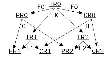
(* See Figure 1 at the end of this file. *)
FSD1* is optimal (or optimum) modulo PR1 and FSD2* is optimal (or optimum) modulo PR2,
BSD1* is optimal (or optimum) modulo CR1 and BSD2* is optimal (or optimum) modulo CR2,
ISD1* is optimal (or optimum) modulo TR1 and ISD2* is optimal (or optimum) modulo TR2,
FSD0* = RES(FSD1*, FSD2*),
BSD0* = RES(BSD1*, BSD2*) and
ISD0* = RES(ISD1*, ISD2*),
then
FSD0* is optimal (or optimum) modulo PR0,
BSD0* is optimal (or optimum) modulo CR0 and
ISD0* is optimal (or optimum) modulo TR0.
Proof of Theorem 4. The proof of this theorem requires only three applications of Theorems 2 and 3 (or Theorem 1), QED.
The Subsystem Tradeoff Functions
Now we must search for an increasing function G such that PFM0R0(FSD01)
= G(PFM0R1(FSD01),
PFM0R2(FSD01)),
for every functional system design FSD01 such that FSD01 = RES(FSD11, FSD21). PFM0R1(FSD01) is interpreted to mean that PFM0R1 is evaluated for the first subsystem of FSD01 so that
PFM0R1(FSD01) = PFM0R1(FSD11) and,
similarly, PFM0R2(FSD01) = PFM0R2(FSD21).
Such a G can usually be defined at the same time as the overall subsystem performance figures of merit, PFM0R1 and PFM0R2, are being defined, in terms of "budgets." For example, if expected speed of service is a performance figure of merit at the top level, then a speed of service figure of merit will be defined (budgeted) for each subsystem such that the sum of the expected values of the speeds of service for the subsystems is the expected value of speed of service for the whole system. The definition depends, of course, on how a service event is broken down between the subsystems and on the interfaces between the subsystems.
Similar comments apply to the characteristics of the increasing functions H and K, so that CR0 is a tradeoff between CR1 and CR2 and TR0 is a tradeoff between TR1 and TR2.
We can also find a functional equation that these subsystem tradeoff functions must satisfy if they are to constitute the hypotheses for Theorem 4.
The Subsystem Tradeoff Functional Equation, Theorem 5: If F0, F1, F2, G, H and K satisfy the hypotheses of Theorem 4, then F0, F1, F2, G, H and K must also satisfy the Subsystem Tradeoff Functional Equation:
F0(G(PFM0R1(X), PFM0R2(X)),
H(CFM0R1(X), CFM0R2(X)))
= K(F1(PFM0R1(X), CFM0R1(X)),
F2(PFM0R2(X), CFM0R2(X))),
for every implementable system design
X = ISD0j such that
ISD0j = RES(ISD1k, ISD2l) for
implementable subsystem designs ISD1k and ISD2k.
Proof of Theorem 5: If F0, F1, F2, G, H and K satisfy the hypotheses of Theorem 4, then, TFM0R0(X)
= F0(PFM0R0(X), CFM0R0(X)), by the definition of F0;
= F0(G(PFM0R1(X), PFM0R2(X)),
H(CFM0R1(X), CFM0R2(X))), by the definitions of G and H.
On the other hand, we also have TFM0R0(X)
= K(TFM0R1(X), TFM0R2(X)), by the
definition of K;
= K(F1(PFM0R1(X), CFM0R1(X)),
F2(PFM0R2(X), CFM0R2(X))), by the definitions of F1 and F2.
These equations yield the Subsystem Tradeoff Functional Equation:
F0(G(PFM0R1(X), PFM0R2(X)),
H(CFM0R1(X), CFM0R2(X)))
= K(F1(PFM0R1(X), CFM0R1(X)),
F2(PFM0R2(X), CFM0R2(X))),
QED.
The Subsystem Tradeoff Functional Equation has at least two solutions:
Two Solutions of the Subsystem Tradeoff Functional Equation, Theorem 6:
Solution 1: For every appropriate pair, (r, s), of real numbers, F0(r, s) = F1(r, s) = F2(r, s)
= G(r, s) = H(r, s) = K(r, s) = r + s.
Solution 2: For every appropriate pair, (r, s), of real numbers, F0(r, s) = F1(r, s) = F2(r, s)
= G(r, s) = H(r, s) = K(r, s) = r * s.
Proof of Theorem 6: Solution 1: If
F0(r, s) = F1(r, s) = F2(r, s)
= G(r, s) = H(r, s) = K(r, s) = r + s, then
F0(G(PFM0R1(X), PFM0R2(X)),
H(CFM0R1(X), CFM0R2(X)))
= F0(PFM0R1(X) + PFM0R2(X),
CFM0R1(X) + CFM0R2(X)), by the definitions of G and H;
= PFM0R1(X) + PFM0R2(X)
+ CFM0R1(X) + CFM0R2(X), by the definition of F0;
= PFM0R1(X) + CFM0R1(X)
+ PFM0R2(X) + CFM0R2(X);
= F1(PFM0R1(X), CFM0R1(X))
+ F2(PFM0R2(X), CFM0R2(X)), by the definitions for F1 and F2;
= K(F1(PFM0R1(X), CFM0R1(X)),
F2(PFM0R2(X), CFM0R2(X))), by the definition of K.
Solution 2: The proof for solution 2 is obtained from that for solution 1 by changing + to *, QED.
Looking for solutions of the Subsystem Tradeoff Functional Equation we should, at least at first, regard the top level requirements, PFM0R0, CFM0R0, TFM0R0 and F0, as fixed because these were presumably developed with the cooperation of the Customer and to change these drastically would require yet another round of negotiations with the Customer. The other functions, G, H, K, PFM0R1, CFM0R1, F1, PFM0R2, CFM0R2 and F2 are under the control of systems engineering, determined by the subsystem architecture and the top level requirements.
Other solutions of the Subsystem Tradeoff Functional Equation exist. If none of these solutions is satisfactory, then it might be possible to change the definitions of PFM0R1, CFM0R1, PFM0R2, CFM0R2, or to change the subsystem architecture or even to go back to the Customer to renegotiate SDR0.
CONCLUSIONS
The allocation of system requirements to subsystems is the crucial step in system functional analysis. In this paper we have discussed an approach to this problem through the concept of tradeoff that will ensure that better designs for the subsystems will result in better designs for the system and, in fact, optimal or optimum designs for the subsystems will result in optimal or optimum designs for the system.
There is a great deal at stake here and it is well worth while for systems engineering to get it right in phase 2 while changes are relatively very cheap to make. After detailed design begins in phase 3, it is way too late.
REFERENCES
Chapman, W. L., Bahill, A.T. and Wymore, A.W., Engineering Modeling and Design, CRC Press, Boca Raton, 1992.
Wymore, A. Wayne, Model-Based Systems Engineering, CRC Press, Inc., 2000 Corporate Blvd., N. W., Boca Raton, FL 33431, 1 800 272 7737, 1993.
AUTHOR BIOGRAPHY
Wayne Wymore earned BS and MS degrees at Iowa State University, and the PhD at the University of Wisconsin, all in mathematics. He is Professor Emeritus of SE at the University of Arizona where he was the first Chairman of the Department of SE and first Director of the Computing Center. While managing, teaching, researching and consulting internationally, he authored A Mathematical Theory of Systems Engineering: The Elements, 1967, Systems Engineering Methodology for Interdisciplinary Teams, 1976, and Model-Based Systems Engineering, 1993. System Functional Analysis and System Design, Phase 2 of Model-Based Systems Engineering is forthcoming.
EXERCISE FOR THE STUDENT
Prove the theorem: If, for i = 0, 1, 2,
Fi(r, s) = ai * r + bi * s, K(r, s) = a3 * r + b3 * s, G(r, s) = a4 * r + b4 * s, H(r, s) = a5 * r + b5 * s,
a4 = a1 * a3 / a0,
b4 = a2 * b3 / a0,
a5 = a3 * b1 / b0 and
b5 = b2 * b3 / b0,
then
F0, F1, F2, G, H, K, satisfy the Subsystem Tradeoff Functional Equation.
Figure 1.
Performance, Cost and Tradeoff Requirements at both the top and subsystem levels are defined in terms of real-valued figures of merit.
F0 is a two-variable increasing function that defines the relation between the top level tradeoff figure of merit and the top level performance and cost figures of merit
F1 is a two-variable increasing function that defines the relation between the tradeoff figure of merit and the performance and cost figures of merit for subsystem 1.
F2 is a two-variable increasing function that defines the relation between the tradeoff figure of merit and the performance and cost figures of merit for subsystem 2.
G is a two-variable increasing function that defines the relation between the top level performance figure of merit and the performance figures of merit at the subsystem level.
H is a two-variable increasing function that defines the relation between the top level cost figure of merit and the cost figures of merit at the subsystem level.
K is a two-variable increasing function that defines the relation between the top level tradeoff figure of merit and the tradeoff figures of merit at the subsystem level.
Would you like to go to Bahill's Systems Engineering Page?